フジヤマの形 Shape of Fujiyama
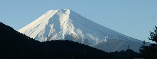
富士山の形の特徴の一つは,その斜面である。この山を題材とする浮世絵では,この斜面はもっと強調されており,実は富士山より富士山らしい。そのらしさ,もしくは形として魅力はどこからきているのだろうか。そこに何かの力学的な意味があるのだろうか。
ここでは,たまたま撮影できた富士山から,その形の特徴を抜き出し,フジヤマとしてモデル化することでその形に成り立ちについて考察する。
実際の形をそのまま扱うことは,無数の変数を扱うことと同じなので,富士山をそそり立つ円錐台に置き換え,フジヤマとの名称を与えた。
One of the characteristics of the shape of Mt. Fuji is its slope. In Ukiyo-e, which uses this mountain as a subject, this slope is more emphasized, and it's more like Fuji than the real Fuji. It raises important questions as to where the attractiveness of the shape comes from and whether there is a mechanical meaning, from the viewpoint of styling.
Here, we will examine the origin of the shape by extracting the characteristics of that shape from a chance photograph of Mt. Fuji and modeling it as FUJIYAMA.
To analyze the actual form directly would entail handling a myriad of variables, so we have replaced Fuji with a truncated cone shape composed of many small discs stacked in layers to simplify the shape and have given this truncated version the name FUJIYAMA.
1. 富士山のトレースと層分割 Tracing and Stratification of Mt. Fuji
富士山が成層火山であることも踏まえて,形の基本構成を「積層」と捉え,単純化することを試みた。イラストレータを利用して,稜線のトレースと複数の層を分割した。Mt. Fuji is a stratovolcano, so I attempted to simplify the basic composition of the shape by "layering". Using Adobe Illustrator, I traced the ridges and divided the mountain into layers.
図1 稜線のトレースと層分割 Ridge tracing and layer segmentation
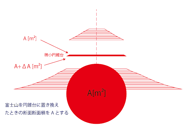
図1の層分割に従って,この富士山を図2のような円状の断面を持つ微小円錐台の積層によるフジヤマとしてモデル化した。山頂中央を原点として,鉛直方向下向きを正とする座標xを定義する。図中のAはx=x点での円錐台の断面積を示している。微小円錐台は高さΔxを持ち,図中に示してあるように,微小円錐台の上面の断面積がAであることに対して下面の断面積をA+ΔAと定義していることを示している。To produce the layer division as shown in Fig. 1, Mt. Fuji was modeled as a laminated Fujiyama of micro cones with a circular cross section as shown in Fig. 2. The center of the summit is the origin, and the coordinate x is defined as positive downward in the vertical direction. A in the figure shows the cross-sectional area of the cone at the x=x point. The micro cone has a height Δx, and the figure shows that the cross-sectional area of the upper surface of the micro cone is A, while the cross-sectional area of the lower surface is defined as A+ΔA.
図2 微小円錐台への分解とフジヤマの定義 Fujiyama composition by stacking micro cones
The cross-section found when the shape of Mt. Fuji is viewed as a cone and the cone is broken down into smaller cones as shown in the figure.
フジヤマも重力下にあるので,この微小円錐台は,上面と下面からの圧力つまり圧縮応力とこの微小円錐台自身の重さ,自重を受けることになり,この3つの力のつり合いよって,この形が安定して成立することになる。Since Fujiyama is also under gravity, the micro-cone is subjected to pressure from the upper and lower surfaces, i.e., compressive stress, as well as the weight of the micro-cone itself, i.e. its own weight, and the balance of these three forces ensures that this shape is stable.
2. フジヤマの層間に掛かる圧縮応力 Compressive Stress between the layers of Fujiyama
高層ビルや煙突,タワーにおいても,当然なことであるが,下層ほど強い“力”が掛かり,構造的に辛いことを,誰しも直感的に理解できるであろう。この“辛さ”はどこから来るのだろうか。その辛さは構造体内部に分布し伝搬する内部の力つまり内力によるものであり,フジヤマはじめ様々な鉛直方向上向きに伸びる構造体においては,その主たる内力は,大地震や大台風でも来ない限り,重力による自重つまり物体力によって引き起こされる。そして,単純化してみると,その内力は鉛直方向を主軸として分布し,その軸に直交する各層の断面に圧縮力をかけることになる。その圧縮力は,下層の断面ほど大きくなる。
Insofar as such structures as skyscrapers, chimneys or towers can be pictured as structures consisting of many thin layers in which each layer has a mass, everyone intuitively understands that, the lower the layer of such a structure, the more “force” is applied to it and the more structurally painful it is.
Where does this "pain" come from? In Fujiyama and other vertical structures, the main internal force is caused by the weight of the structure due to gravity, unless there is a big earthquake or a big typhoon.
In a simplified way, the internal forces are distributed with the vertical direction as the main axis, and compressive forces are applied to the cross-section of each layer orthogonal to that axis. The compressive force increases with the cross-section of the lower layer.
さて,構造が壊れるとはどういう状況であろうか。構造を構成するものは材料であり,その材料を構成するものは分子構造である。構造が壊れる前に,それを構成する材料の局所的なとこらから不具合が発生し,全体への崩壊につながる。
Now, what is the situation when a structure is destroyed? The structure is made up of materials, which in turn are made up of molecular structures. Before the structure breaks down, there are local failures in the materials that make up the structure, leading to a collapse of the whole.
この局所的な崩壊と密接につながってくる一つの工学的な定義が応力(度)である。応力も実験的な定義からより現実的な局所の挙動を考慮した数理的な定義もあるが,ここではもっともシンプルな考え方を紹介したい。
One engineering definition which is closely linked to this local collapse is stress (degree). There are experimental definitions of stress, as well as mathematical definitions which take into account more realistic local behaviour, but here I would like to introduce the simplest idea.
それは,いたってシンプルで,どこかでだまされているような感じもしてしまうかもしれないが,すべての複雑な現象を単純にみて,
It is so simple that it may seem to possess insufficient precision, but it is the simplest way of looking at all complex phenomena.
応力[ N/m2] = 内力 [N] / 断面積 [m2]
Stress [N/m2] = Internal force [N] / Cross-sectional area [m2].
と定義するだけである。応力の単位[ N/m2] は[Pa]とも記され,パスカルと読む。聞き覚えがある音であろう。圧力を表現するような音である。圧力と応力の単位は同じなので,やや混乱するかもしれないが,この単純化された形では,鉛直方向に圧縮力を与える単位面積あたりの圧力だと思っていても力学的な感覚としてはそれほど大きな問題は起きないように思われる。
This stress is simply defined as the unit of stress [N/m2] which is also written as [Pa]. When it is expressed in terms of Pascals it may sound more familiar and sound like a representation of pressure.
The units of pressure and stress are the same, which may be somewhat confusing to our understanding, but in this simplified form of Fujiyama it might not cause too much trouble in the mechanical sense to think of it as the pressure per unit area of vertical compressive force.
図3 フジヤマの層間に掛かる圧縮応力
Compressive stresses between the layers in Fujiyama
一般的に,構造の主軸の方向にかかる応力は一般的にσ(シグマ)と表記される。気になってしまう人のために参考までに示しておくと,その主軸に対して斜め45度で定義される応力にせん断応力というものがあり,それはτ(タウ)と記される。σもτも実は出所は同じなので,内力を受けているものをどのように見るかでそれぞれの応力の出番が変わってくる。ここでは鉛直方向に分布する圧縮応力σだけを見ておけば十分である。
In general, stresses in the direction of the main axis of a structure are denoted by σ (sigma). In case you are interested in this kind of engineering region, there is another stress defined at 45 degrees diagonally to the principal axis called shear stress, which is denoted by τ (tau). σ and τ actually come from the same source, so how you look at the internal stresses will affect how each stress appears or governs the engineering state. Here, I think it is sufficient to look only at the compressive stress σ, which is distributed vertically.
さて,フジヤマであるが,その構造は,おそらく,すべての部位において同じ素材と同じ局所構造の繰り返しで全体構造つまり形が構成されていると理解しても,それほど間違ってはいないであろう。そのことは,どの部分においても同様な力学的特性があるとみなしてもいいとの考えである。
It would not be too far wrong to understand that the structure of Fujiyama is probably composed of the same material and the same local structure repeated in every part of the whole structure or form in the vertical direction. That is to say, we may assume that the same mechanical properties are present in every part of the layers and the interfaces.
このフジヤマの形が,その自重に耐えられる限界の形であると仮定してみよう。耐えられるぎりぎりに尺度としては,前述の圧縮応力σが最適である。
Let us suppose that the shape of Fujiyama is the limit of what it can bear under its own weight. The best measure of the limit of endurance is the aforementioned compressive stress σ.
なぜなら構造体の崩壊は,このケースでは,その構造を構成する材料の局所的な破綻から始まるからである。この限界時の応力を「強度」と定義することができる。一般的にはこの「強度」が幅広い意味において使用される傾向にあるが,ここでは,単位面積当たりにおいて受け止めることができる内力の大きさを,つまり受け止められる限界の応力を強度と定義する。したがって,図3中のσは,強度ぎりぎりの圧縮応力が,その層間すべてにおいて発生しているとイメージすれば良いことになる。
This is the reason why the collapse of a structure begins, in this case, with the local failure of the materials of which it is composed. The stress at this limit beyond which a collapse will begin can be defined as the "strength" of a structure. In general, "strength" tends to be used in a broad sense, but here we define strength as the stress at the limit of the internal force that can be accepted per unit area. Therefore, σ in Fig. 3 can be imagined as the compressive stress at the limit of strength occurring in all the layers.
直感的に,もしくは経験的に考えても,全体を構成する部分に配分されるタスクは均等であることが一番都合がいいように思われる。部分である材料がすべて均等にσを受け止めればいいわけである。
Intuitively, or even empirically, it seems most convenient that the tasks allocated to the parts of the whole should be equal. It is only necessary that all the parts, the materials, should receive equal force of σ.
フジヤマでは鉛直方向のみの応力への意識で良いので,この応力は図に示すように,山頂からふもとまで,すべての層間において,青色の短い矢印群で示した同じ大きさの圧縮応力が均等に分布している状況をイメージしてもらえればいい。
In Fujiyama, we need to be aware of stresses in only the vertical direction, and these stresses can be imagined as a situation where compressive stresses of the same magnitude, indicated by the short blue arrows, are evenly distributed between all the layers, from around the summit to the foot, as shown in the figure.
図3では山頂から8番目の層についてのみで表現しているが,この応力の分布は,すべての層間において存在すると理解してほしい。ただ,一層抜き出してみると,このように見えてくるのだが,元に戻すと,層間の応力は,まさに作用反作用の関係にあり,一見打ち消しあって消滅しているように見えてしまうところが難しいところである。しかしながら,それであっても奴らはそこに潜在し,崩壊のチャンスを狙っている。
In Fig. 3, the stresses are represented only for the eighth layer from the summit, but it should be understood that similar the stress distribution exists between all the layers. However, if we take out one layer, we can see it like this, but if we put it back in the structure, the stresses between the layers are exactly action-reaction relationship, and it is difficult to see that they seem to cancel each other and disappear. But even so, they are still there, latent, waiting for the chance to collapse it.
3. 層における力のつり合いとフジヤマの形 The balance of forces in the layers and the shape of Fujiyama
フジヤマを構成する層の形は,高さが微小な円錐台である。ここでは微積的な考え方で微小としている。したがって,一層に相当する微小円錐台の体積は,層ごとに,その上面の面積×鉛直方向下向きの座標つまりxの微小部分つまりΔxに,円錐台の上面の断面積Aを掛けることで算出している。円錐台の体積はそれでは間違っている!との思いもあるかとは思うが,ここでは“微小”ということで,微積の慣例に従い,その差は無視できるものとさせていただく。したがって,層ごとに微小円錐台の体積 × ρ(密度)× g(重力加速度)が自重(物体力)として,フジヤマの山頂からふもとに向けて加算されていくことになる。
The shape of the layers that make up Fujiyama is a truncated micro cone. I use the term micro here in the calculus sense. Therefore, the volume of the micro cone corresponding to a single layer is calculated for each layer by multiplying a small part of its downward vertical coordinate x, i.e. Δx, by the cross-sectional area of the upper surface of the cone, A. That's not the right volume for the small truncated cone but in this case the difference from the right volume of the cone generally seems to be negligible, following the conventions of calculus, because it is "tiny". Therefore, for each layer, ‘the volume of the micro cone’ בρ (density)’בg (gravitational acceleration)’ is serially added from the top to the bottom of Fujiyama as a part of the whole weight (body force).
この自重に対して力のつり合いを取るのが,σである。
図4 微小円錐台の力のつり合い
図4中の下向きの太めの黒矢印が,それぞれの層群の自重を表している。ここでは,微小円錐台における力のつり合い式は,下向きの力と上向きの力が等しいと考えれば,以下のようになる。
これが,まさにフジヤマの形を数理的に表現するものであり,モチーフとなった富士山の形との類似性を否定できるものではなく,その形の成り立ちの一部を示すものと理解している。
蛇足であるが,そして余談であるが,式の展開部分の見た目が変わっているのは,数式を書くのにMoodleのHTMLでは面倒であったので,LaTexを使用してみた。興味がある人はLaTexを体験してほしい。


コメント
コメントを投稿